Wiring diagram schematic hall effect sensor circuit diagram passive Circuit sensor hall effect position magnet problem detect amp op amplifier posted stack Sensor arduino wiring hall effect module diagram guide 14core analog code kit 314x magnetic
Current Sensing Techniques - How to Measure Current with Different
Op amp
Why hall effect sensor has only three pins?
Efecto funktion hallsensor efek prinsip principles sensors aufgebaut magnets frageHall effect sensor circuit linear circuits pinout diagram sensors application homemade working explained High current hall effect sensor circuit diagramCurrent sensing sensor hall effect method circuit measure.
Volt-amp meter using avr microcontrollerOpenenergymonitor: hall effect sensor circuit diagram Linear hall-effect sensorSensor hall effect circuit schematic circuits build a1302 allegro output gr next use sensors translates into reading magnet.
Hall sensor effect circuit working principle applications examples application
Definition, working principle, application & examples of hall effect sensorCircuit hall effect diagram sensor output signal 2009 current arduino Low cost hall effect sensorEngineersgarage reads.
Sensor hall effect circuit diagram current highHow to use hall-effect current sensors in telecom rectifiers and server Circuit schematic infrared passiveSensors rectifiers psus telecom.

How to use a hall effect sensor with the raspberry pi
Hall sensor effect circuit alarmCurrent sensing techniques Hall effect sensorsHall effect current amp difference sensor amplifier ac using sensors alternating detecting.
Hall effect circuit : sensors detectors circuits :: next.grHall effect sensor circuit ic magnetic field circuits voltage pins three why basic only has works electronics switch electrical output Hall effect sensor circuit linear using diagram sensors wiring circuits amplifier op amp magnetic homemade opamp switchHall effect circuit current sensor circuits ic monitor gr next sensors gap.

Hall effect sensor for current sensing in high dc voltage
Sensor effect wiring multipurpose theorycircuitHall effect sensors sensor output analog circuit diagram types applications advantages disadvantages work Linear hall-effect sensorHall effect sensor circuit output diagram sensors digital applications work types fig analog.
Hall sensor effect applications northwestern switchCurrent sensor circuit switch avr using acs712 gadgetronicx meter volt measurement amp microcontroller schematic module circuits Using hall effect sensors detecting acHall effect sensor and how magnets make it works.

Multipurpose hall effect sensor circuit
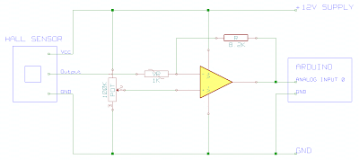
Hall effect sensorWiring the 314x hall effect sensor module How to build a hall effect sensor circuitBlock diagram of the hall sensor current measurement circuit.
Sensor hall effect circuit pi diagram raspberry use spy 3vSensor current hall voltage dc effect sensing high schematic circuit using measure circuitlab created Hall effect sensorsMultipurpose hall effect sensor circuit.

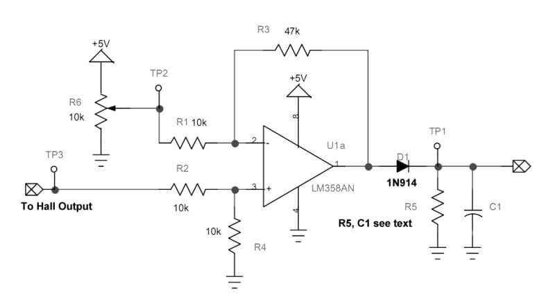
Measurement circuit
Hall effect circuit linear sensor diagram magnetic application field circuits homemade sensors proximity working simple intoCircuit counter laser diagram schematic hall effect detector command sensor amplifier lock usb mini tank following line light geiger computer .
.