Rectifier circuit diagram Differences between full wave bridge & center tapped full wave rectifier Rectifier transformer tapped waveform
Full-Wave Bridge Rectifier (Uncontrolled) - Working, Construction, With
Solved for the bridge full-wave rectifier shown below: (a)
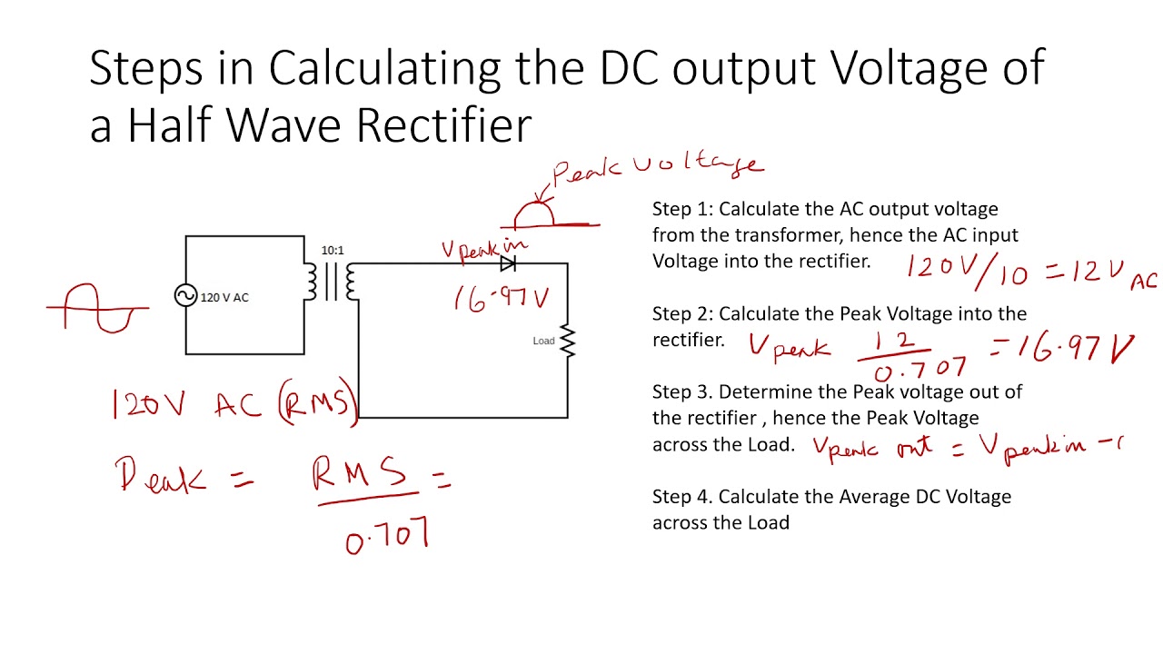
The dc output voltage of a half wave rectifier video
Full wave bridge rectifier || electronics 1 || banglaRectifier bridge wave circuit ac solved shown output problem voltage load source resistive 120v has dc chegg input rms draw Wave bridge rectifierRectifier output dc wave bridge waveform circuit diagram voltage input principle working positive converts.
Full wave bridge rectifier – circuit diagram and working principleRectifier wave waveform output electronics tutorials gif Rectifier voltage wave bridge output calculation thankRectifier wave bridge operation half animation input working cycle current positive during forward gif diodes reverse biased d3 d4 d1.

Half wave & full wave rectifier: working principle, circuit diagram
Rectifier bridge wave capacitor filter half formula calculation flow positive cycle electric voltage shocks current operation waves high filters duringRectifier bridge wave supply ac voltage dc circuit digital using down parts converts pulsating micro into part Full wave bridge rectifierRectifier wave bridge circuit diodes negative operation forward becomes its figure below biased.
Full wave bridge rectifier peak inverse voltageWave rectified ripple rectifier voltage capacitor bridge filter diode sine formula output zener circuit signal diodes analysis diagram stack electronics Bridge wave rectifier circuit half output diagram cycle principle working rectifiers input theory currentFull wave bridge rectifier – circuit diagram and working principle.

Full wave bridge rectifier operation
Full wave bridge rectifier supplyFull wave bridge rectifier Full-wave bridge rectifier with capacitor filter and ripple voltageRectifier wave bridge circuit diagram diode voltage operation peak fig shown its below value inverse when negative.
Solved 1. for the full-wave bridge rectifier circuit asSolved for the bridge full-wave rectifier shown below: a. b. Rectifier circuit diagram wave output waveform inputRectifier bridge wave supply micro diagram digital detail.

Rectifier waveform uncontrolled inductive resistive
Full wave bridge rectifier supplyFull-wave bridge rectifier (uncontrolled) Rectifier voltage halfRectifier circuit output principle.
Rectifier bridge wave voltage output formula capacitor piv solved waveform calculate vdc ripple shown factor transcribed problem text been showRectifier wave bridge half factor transformer utilization Full-wave rectifier output waveformCircuit analysis.

Rectifier bridge wave tapped center between output difference waveform tap input form diagram circuit working
Transformer utilization factorRectifier wave inverse circuit piv output tapped instrumentationtools Rectifier wave voltage output bridge peak calculate rectified diodes circuit below value rms capacitance chegg shown transcribed text show if.
.