Adder logic wiring calculators Half adder circuit: theory, truth table & construction What is half adder and full adder circuit?
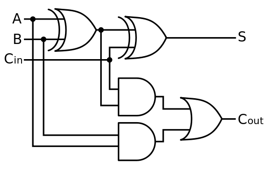
Circuit diagram of a one-bit full adder using the proposed technique in
Digital electronics part i : combinational circuits
Adder elprocus
74hc83 full adder ic pinout, datasheet, equivalent & workingAdder circuit diagram schematic bit works figure Adder circuit construction binary circuits ibm sourav guptaEdacafe: power, accuracy and noise aspects in cmos mixed-signal.
Full adderIc adder bit diagram datasheet pinout Full adder circuit: theory, truth table & constructionFull adder circuit diagram: a complete tutorial.

Adder figure diagram
13+ full adder block diagramAdder circuit carry sum simplified implementation electronics logic output two outputs tutorial combinational circuits both shows below figure Circuit diagram of a one-bit full adder using the proposed technique inFigure 1: schemaric of a full adder.
Full adder logic diagramAdder circuit electronics outputs Adder circuit logic schematic circuitglobe circuits fig sum compressor robhosking shown combinationalCd4008 4-bit full adder ic pinout, working, example and datasheet.

Adder cmos circuit diagram fa transistor using 28t transistors implementation edacafe transmission gate power fig www10 phdthesis book
Adder cmos soiAdder combinational electronics circuits constructed adders wider Full-adder circuit, the schematic diagram and how it works – deeptronic.
.