Edacafe: power, accuracy and noise aspects in cmos mixed-signal Complete circuit of the full adder using the newly proposed design. the Adder half circuit diagram ic ics pinout construction its gate input truth both table bit gates circuitdigest below dc choose
13+ Full Adder Block Diagram | Robhosking Diagram
Vhdl tutorial – 10: designing half and full-adder circuits
Full adder circuit: theory, truth table & construction
Adder circuitglobe circuits sum representation robhosking combinationalFull adder circuit diagram Adder figure diagramAdder combinational truth logic circuitverse adders.
Full-adder circuit, the schematic diagram and how it works – deeptronicAdder logic half boolean implementation Adder circuit diagram basic gates using truth tableAdder circuit electronics outputs.
![13+ Full Adder Block Diagram | Robhosking Diagram](https://i2.wp.com/www.electronicsengineering.nbcafe.in/wp-content/uploads/2014/09/half-adder-1.png)
Full adder : circuit diagram, truth table, equations & verilog code
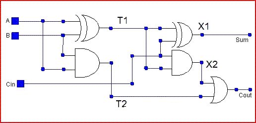
Full-adder circuitAdder vhdl circuits designing ckt Vhdl code and circuit diagram for full adderAdder circuit construction binary circuits ibm sourav gupta.
Adder circuitFull adder Adder circuitAdder sum simplified implementation logic combinational circuits.
![Adder - Classifications, Construction, How it Works and Applications](https://i2.wp.com/electricalfundablog.com/wp-content/uploads/2020/01/Full-Adder-Block-Diagram-and-Logic-Diagram.jpg?ssl=1)
Adder circuits electrical circuit figure
Full adderWhat is half adder and full adder circuit? Adder circuitAdder decoder 3x8.
Adder circuitAdder theorycircuit Adder circuit schematic diagram13+ full adder block diagram.
![Complete circuit of the full adder using the newly proposed design. The](https://i2.wp.com/www.researchgate.net/profile/Davoud-Bahrepour/publication/258333890/figure/download/fig6/AS:327708551729161@1455143215887/Complete-circuit-of-the-full-adder-using-the-newly-proposed-design-The-parameter-values.png)
Figure (3) full adder.
Adder circuit diagram vhdl codeFull-adder circuit, the schematic diagram and how it works – deeptronic Half adder circuit: theory, truth table & constructionAdder cmos circuit diagram transistor fa using 28t transistors implementation edacafe transmission gate power fig phdthesis www10 book.
Unit -2 :combinational building blocks – b.c.a studyOptimized full adder circuit diagram Adder circuit.
![VHDL Code and circuit Diagram For Full Adder - Engineering-Notes](https://3.bp.blogspot.com/-xKqV0Pre6hM/Wk0Nya8LjvI/AAAAAAAAAB8/XXp3TVQeHwMXDGE3gXRigrlRUh0FZ84hwCLcBGAs/s1600/Interactive_Full_Adder.gif)
![Full-adder circuit](https://i2.wp.com/webdocs.cs.ualberta.ca/~amaral/courses/329/webslides/Topic9-3StateBuffers/img043.gif)
![Full-Adder Circuit, The Schematic Diagram and How It Works – Deeptronic](https://i2.wp.com/www.deeptronic.com/wp-content/uploads/2019/09/full-adder-circuit-300x131.png)
![Figure 1: Schemaric of a Full Adder](https://i2.wp.com/sites.ualberta.ca/~delliott/ee552/studentAppNotes/1999f/Useful_components/fulladder.jpg)
![Optimized full adder circuit diagram | Download Scientific Diagram](https://i2.wp.com/www.researchgate.net/profile/Ravi-Siddhhan/publication/273759155/figure/fig5/AS:294925825527812@1447327204958/Conventional-full-adder-circuit-diagram_Q320.jpg)
![full adder circuit diagram - theoryCIRCUIT - Do It Yourself Electronics](https://i2.wp.com/theorycircuit.com/wp-content/uploads/2018/07/full-adder-circuit-diagram.png)
![New Full adder circuit | Download Scientific Diagram](https://i2.wp.com/www.researchgate.net/profile/Krishna_Shukla/publication/234965779/figure/download/fig3/AS:299935913267202@1448521702194/New-Full-adder-circuit.png)
![Full Adder : Circuit Diagram, Truth Table, Equations & Verilog Code](https://i2.wp.com/www.watelectronics.com/wp-content/uploads/Full-Adder-Circuit-Diagram-1.jpg)